How to Efficiently Power Tiny Industrial Sensors
June 25, 2019
| By: Reno Rossetti Principal Writer, Maxim Integrated |
Inside today’s increasingly automated and electrically harsh industrial environments, you’ll find sensors everywhere (Figure 1). They’re getting more sophisticated, but also smaller. Their complexity requires on-board switching regulators to deliver power more efficiently for minimal heat generation. Yet, there lies the challenge: how do you deliver low-voltage power to these tiny sensors safely while they operate in high-voltage industrial environments? And how do you do so while keeping the solution size small and maximizing efficiency?

Figure 1. Welding in Automotive Assembly Line
Delivering Power Safely
The sensor ”box” includes a front-end transceiver that handles data and routes the power to a step-down buck converter, which delivers the appropriate voltage to the ASIC/microcontroller/FPGA and sensing element. The sensor is typically powered by a 24V DC power source (VBUS). Figure 2 presents the power path.
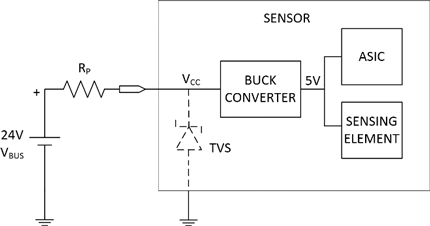
Figure 2. Sensor Power System
Factory floors can be very challenging places when it comes to power management. High-voltage transients abound, given the long cables and strong electromagnetic interference in these environments. As a result, the step-down converter inside the sensor must withstand voltage transients much higher than the sensor operating voltage.
A typical sensor power management solution utilizes transient voltage suppressors (TVS) to limit the input voltage (VCC) of the front-end buck converter. The associated input current peaks are reduced by the resistor RP, a parasitic or physical element in the electric path between the voltage transient’s source (VBUS) and the sensor.
To illustrate our points, let’s consider selecting a TVS out of the LittelfuseTM catalog. Figure 3 presents the general characteristics of a TVS.

Figure 3. TVS V-I Characteristics in Sensor Power System
The TVS device is an open circuit until the voltage across it reaches VBR. At this point, it starts to conduct current while its voltage rises slightly up to its maximum clamping voltage VC, which corresponds to the maximum allowed peak pulse current IPP. The product VC x IPP is the maximum peak power that the TVS can handle (400W for this TVS family).
For effective protection, the TVS VBR must be chosen to be above VCC(MAX) while VC must be below the switching regulator input voltage breakdown.
Ideally, with a 60V-rated buck converter, a SMAJ33A with a minimum VBR of 33V can be used (and a clamp voltage VC of 53.3V, well below 60V). This gives an operating margin of 6.6V above VBUS(MAX) and 6.7V below 60V (Figure 4).

Figure 4. Ideal TVS Selection
Now, let’s consider a unique new way to address the space constraints: vertical integration of the inductor on top of the IC. The MAXM15064 Himalaya uSLIC module (Figure 5), which operates over a wide temperature range from -40°C to +125°C, is available in a low-profile, compact, 10-pin, 2.6mm x 3mm x 1.5mm package.
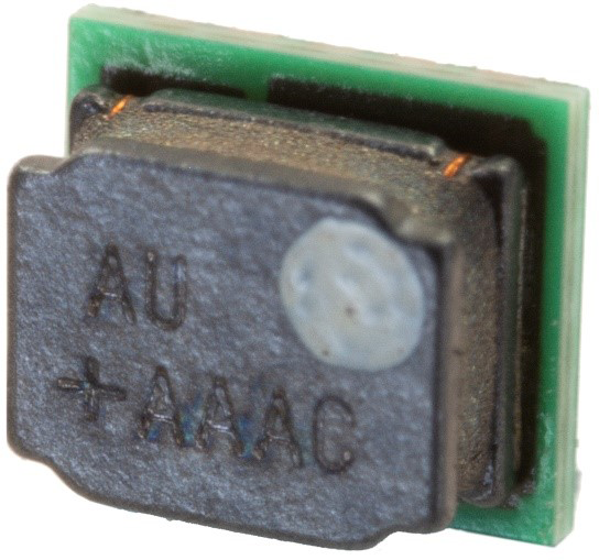
Figure 5. 60V, 300mA Himalaya uSLIC module
Figure 6 shows the dramatic size reduction achieved with the 300mA, 60V buck converter module. The vertical integration of the inductor results in a net component area of just 21mm2.

Figure 6. Vertical integration of the inductor in the MAXM15064 Himalaya uSLIC module enables a dramatic size reduction.
Summary
Industry 4.0 technologies are infusing factories and other industrial environments with the ability to do more with less human intervention. Smart sensors play a critical role in this, but they come with unique power management challenges. The uSLIC power module presents a tiny, high-efficiency, low-EMI buck converter that’s ideal for powering the tiny sensors that bring industrial applications to life.